The purpose of this personal project was to develop a better understanding of character rigging, animation, and the mechanical design of animated figures. What better figure to work on than the Stranger Things Demogorgon. The figure is animated and designed with the intent of being an element in an attraction scene lasting 10-15 seconds.
Character Rigging
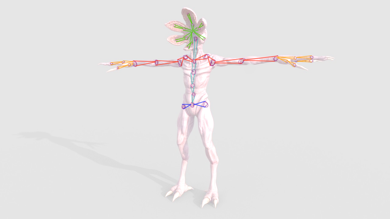
Sketching the intended rigging joints of the figure

I downloaded the Demogorgon Maya file to use as a basis for rigging, I could not find a figure in a T-Pose position, so rigging was a bit more difficult without using the principles of symmetry.


Above is the preliminary rigging setup. Even though the legs do not animate for the intended project, I rigged them for the practice.


This is a close up view of the rigging structure for the head/face. I created inverse kinematic (IK) handles between the root and tip of each "petal" in the head in order to create a fluid animation.

Painting weights of each bone in the rigged skeleton proved to be a rigorous, but interesting task. Since I did not model the Demogorgon, I had no control over the initial meshing. The creator of the model already deformed the muscles based on the figure's initial pose, so by adjusting the skin weights at each bone, I adjusted how the skin physically reacted to rig.
Character Animation
The figure is animated and designed with the intent of being an element in an attraction scene where guests encounter the Demogorgon briefly. Ideally guests in a ride vehicle would be "swatted" away when the figure strikes. The basis of this animation was used to determine the number of functions desired in the mechanical design of the figure.
Mechanical Design
Initial Sketch
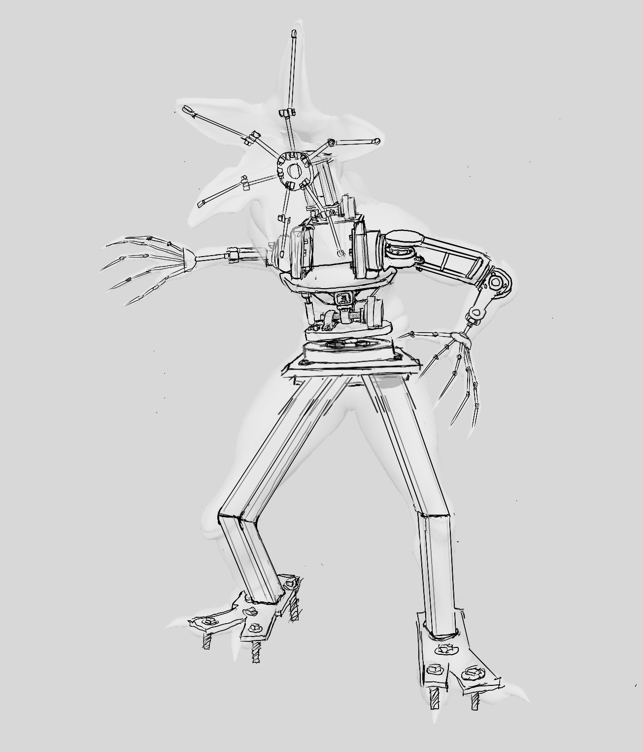
Above is an initial sketch of the mechanical design of the figure. The intention of the sketch was to gain intuition on how different systems would interface spatially. Once I began designing in SolidWorks, certain flaws became apparent in the sketch, which accounts for the difference between the initial sketch and the final CAD model.
SolidWorks Model Overview
Master Assembly


The purpose of this aspect of the project was to focus on the mechanical design of the figure, specifically designing for manufacturability, selecting motors, hardware, and bearings, and designing within spatial constraints. In reality, more of an emphasis would be placed on the design of the character shells, the shell attachments, and control system hardware, but those elements were not addressed in the design.
The mechanical components of the design are color coded, where yellow is AL 7075 & 6061, green is ASTM A36 & A500, orange are bearings, red are motors, dark pink is 3D printed glass-filled nylon, turquoise is polypropylene, and purple is hardware.
Leg Assembly


Given the geometry of the figure's legs, supplemental tubing members were added. These members would be painted a dark black and covered with background facade so that the members would be out of guest sight. Each member is 1.63" ASTM A500 tubing with 0.25" wall thickness.
Arm Assembly


Each arm consists of two motors that allow for elbow extension/retraction and the ability to raise/lower the arm. The hands were left static in this figure, so the hands consist of a 3D printed glass-filled nylon.
Torso Assembly


The torso consists of four motors that create motion in the figure's arms, neck, and torso. It consists of a group of riveted AL 7075 plates with a vacant center to account for the placement of theoretical control system hardware and cabling. To account for misalignment due to manufacturing/assembly tolerances, a spherical bearing was selected at the torso base. The hollow base of each motor allows ease of cable routing through the respective pivots.
Head Assembly


The head of the figure consists of six motors to create head pitch and roll while creating tentacle-like petal articulation. Given the concentration of motors located in this assembly, vacant space was created in the front base for an additional set of control system hardware.
Mechanical Functions
Torso Yaw


Direct drive is used to rotate the upper half of the animated figure (yaw).
Torso Pitch


Direct drive is used to rotate the upper half of the animated figure (pitch).
Elbow Extension/Retraction


A four-bar linkage system is used to allow the forearm to extend and retract about the elbow.
Arm raise/roation


Two functions are being displayed simultaneously: raising and rotating the arm. The arm can be rotated by the motor located inside the torso of the figure, while the arm can be raised by the motor located in the shoulder position.
Head Pitch & Roll


The head pitch and roll functions by the use of a gimbal system. Synchronous unidirectional rotation by each motor will cause the head to roll, while synchronous opposite rotation by each motor will cause the head to pitch. A machined ASTM A36 steel piece serves as the body of which the head rotates about, where spherical bearings are used to house the rotation.
Petal Articulation


Each petal would have four functions: open, close, spline-open, and spline-close. To create the tentacle articulation, 1/8" aircraft cable would be tied off in a bunch at each motor lever arm and fed through the journals. For the spline motion, the cable would be tied off half the length up the petal, while for the full open and close, the cable would tie off at the end of the petal. The tentacle articulation would be the same for each petal given the use of four motors, instead of a set of motors for each petal.