
While taking Mechanical Design I during my Fall 2019 semester, our professor tasked us students with a final project to prove to him that we learned principles of mechanical design. The project was open-ended, which allowed students to design a mechanical system incorporating as many topics covered in the course as possible. I had the pleasure to work with Daniel Wong, Andrew Tumlin, and Jhon Ibanez to design and analyze a rollercoaster restraint system in terms of static and fatigue factors of safety.
Given that our professor wanted to test us on our ability to incorporate the course material, the design of the system emphasized the inclusion of these elements as opposed to some of the traditional methods used in the design of constraint systems. For example, a ratchet and pawl system was used instead of a hydraulic system, and extension springs were used instead of gas shocks.
Design Overview
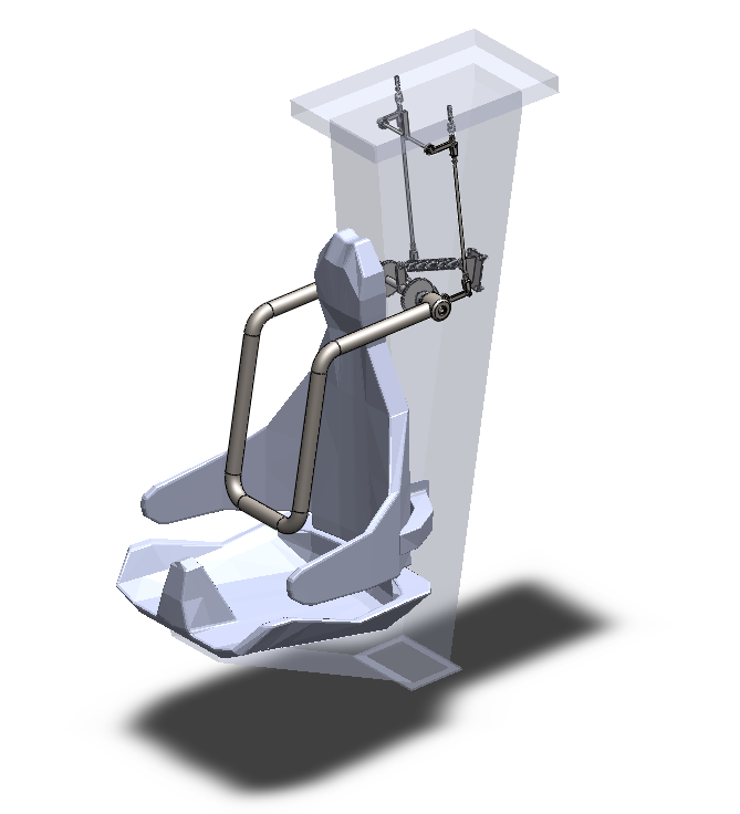

The topics chosen to incorporate into the design from the course curriculum were bearing selection, shaft design, gear design (ratchet and pawl system), and spring design. Given that the project was being evaluated in terms of the mechanical design, the vehicle seat model was provided by themed entertainment CAD modeler Tom Renouf. The vehicle seat was used as reference geometry to determine the approximate sizing of the mechanical components in the system. Given that the seat served as reference geometry, all bearings were pressed into the walls of
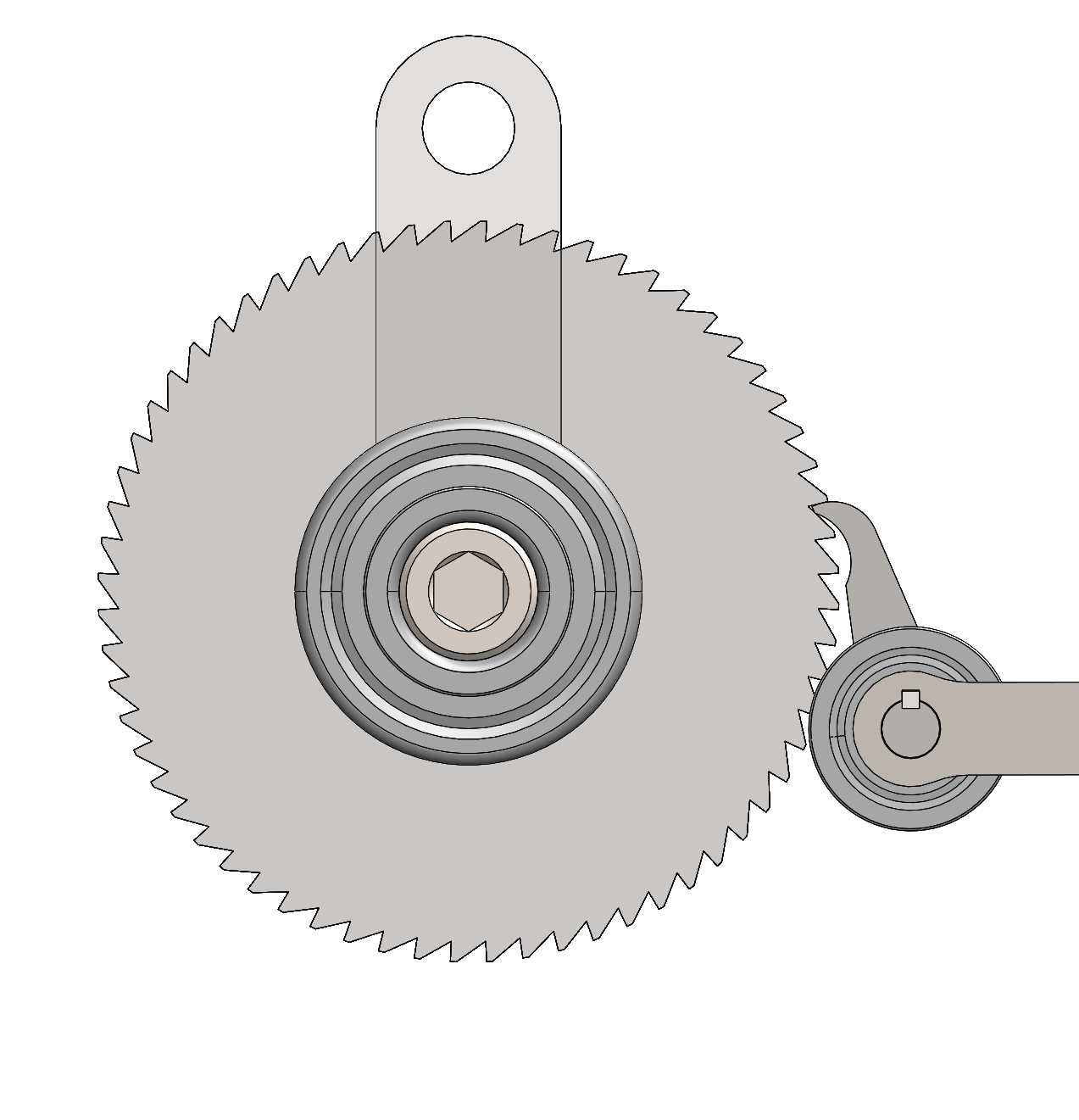
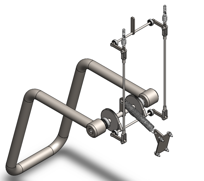
The designed rollercoaster restraint system employs a dual ratcheting mechanism to secure a rider beneath an over the shoulder restraint. Two unidirectional ratcheting gears are used in conjunction with two pawls to allow the restraint to lower over the patron while restricting the upward motion of the restraint during the ride duration.
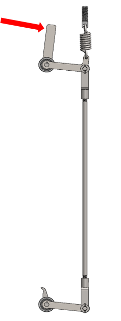

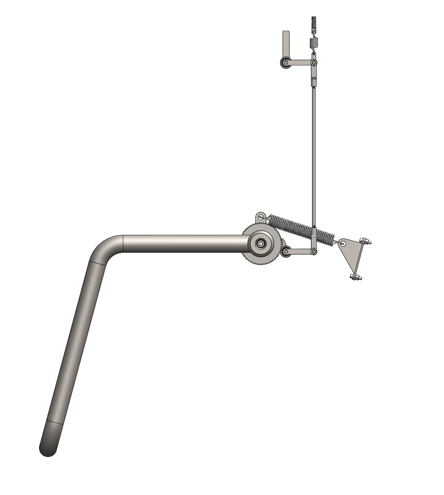
The pawls engage the ratchet from a spring induced four-bar linkage system. As a force is provided to the member on the top linkage shaft, a torque is caused which disengages the pawl from the ratchet. The resistive spring force from the extension springs keep the pawls engaged. Theoretically, the applied force would come from a cam-roller mechanism within the train station once the vehicle has finished its ride duration.
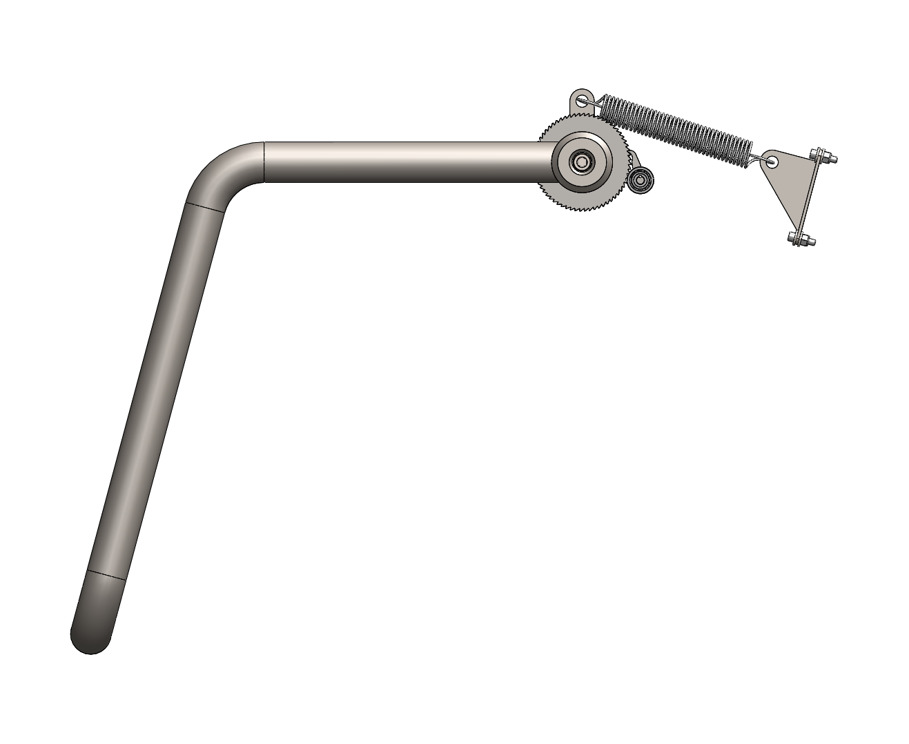
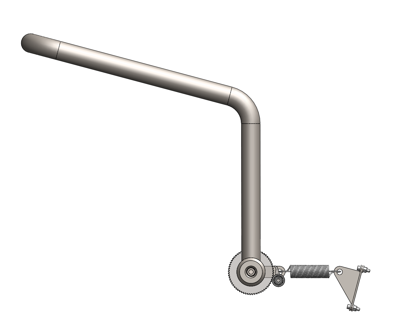
Upon disengagement of the ratchet and pawl system, an extension spring raises the restraint tubing. The extension spring is anchored to a clevis weldment and a clevis member keyed to the ratchet axle.


From left to right illustrates the open configuration with the pawl initially disengaged to the pawl engaged.

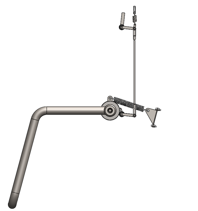
From left to right illustrates the closed configuration with the pawl initially engaged to the pawl disengaged.
failure Mode Analysis
Fatigue
A typical rollercoaster runs cycles every 3 minutes, 16 hours a day, 365 days a year for 20 years. These assumptions were made to test whether the restraint mechanism will remain intact during its lifespan. Every time a vehicle cycles, the lap bar rotates up and down once for riders to get in and out of the ride vehicle. This motion induces some stresses on the restraint mechanism caused by the spring forces that rotate the lap bar up and hold the pawls in place, therefore a fatigue analysis on each component of the mechanism was performed.
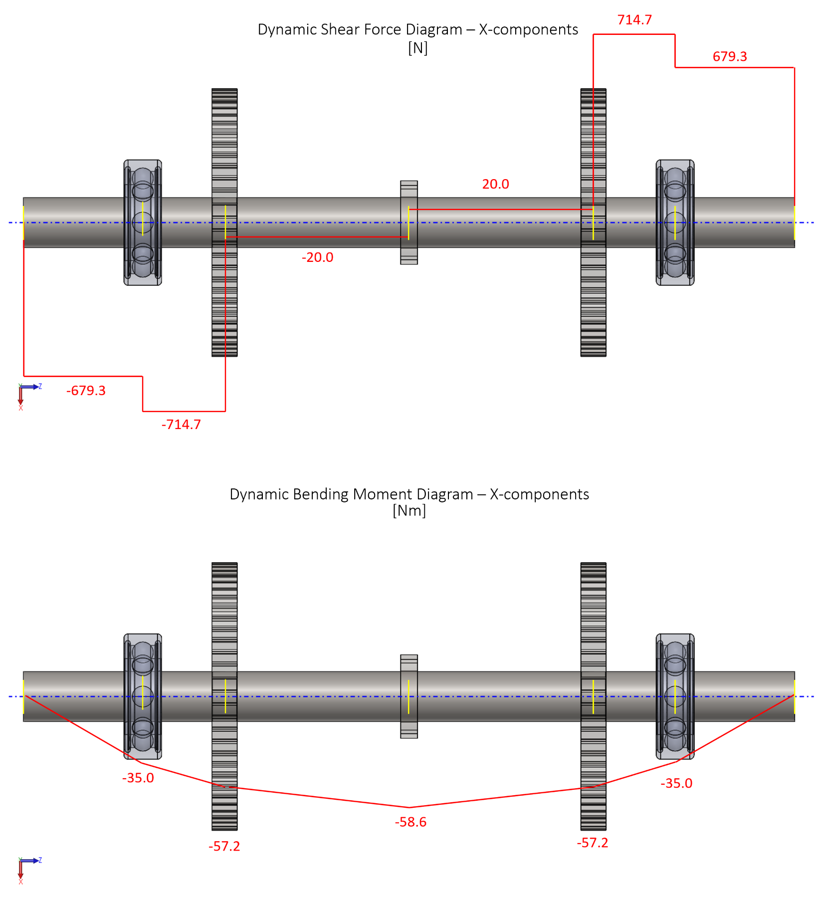
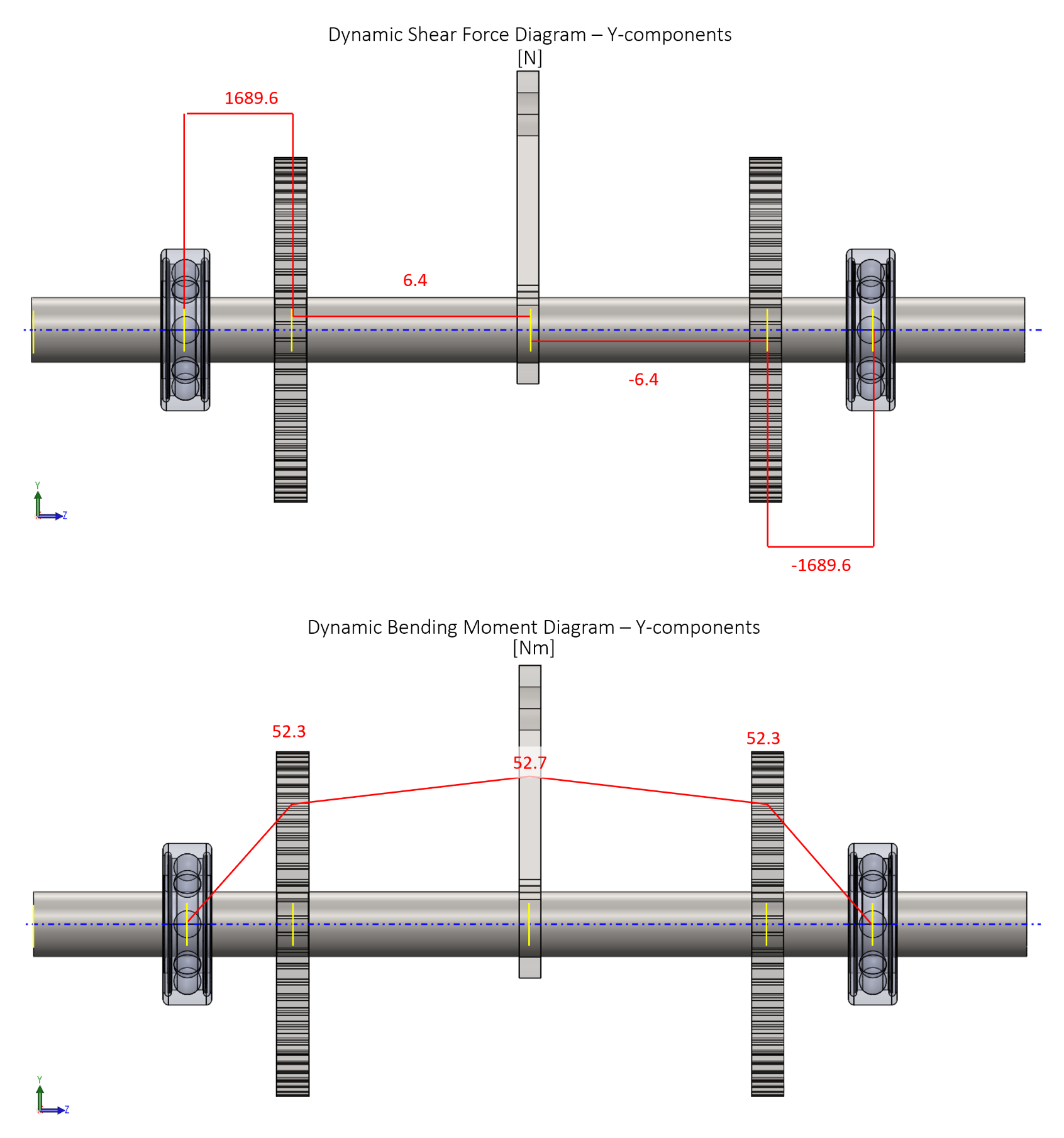
Fatigue - Axles
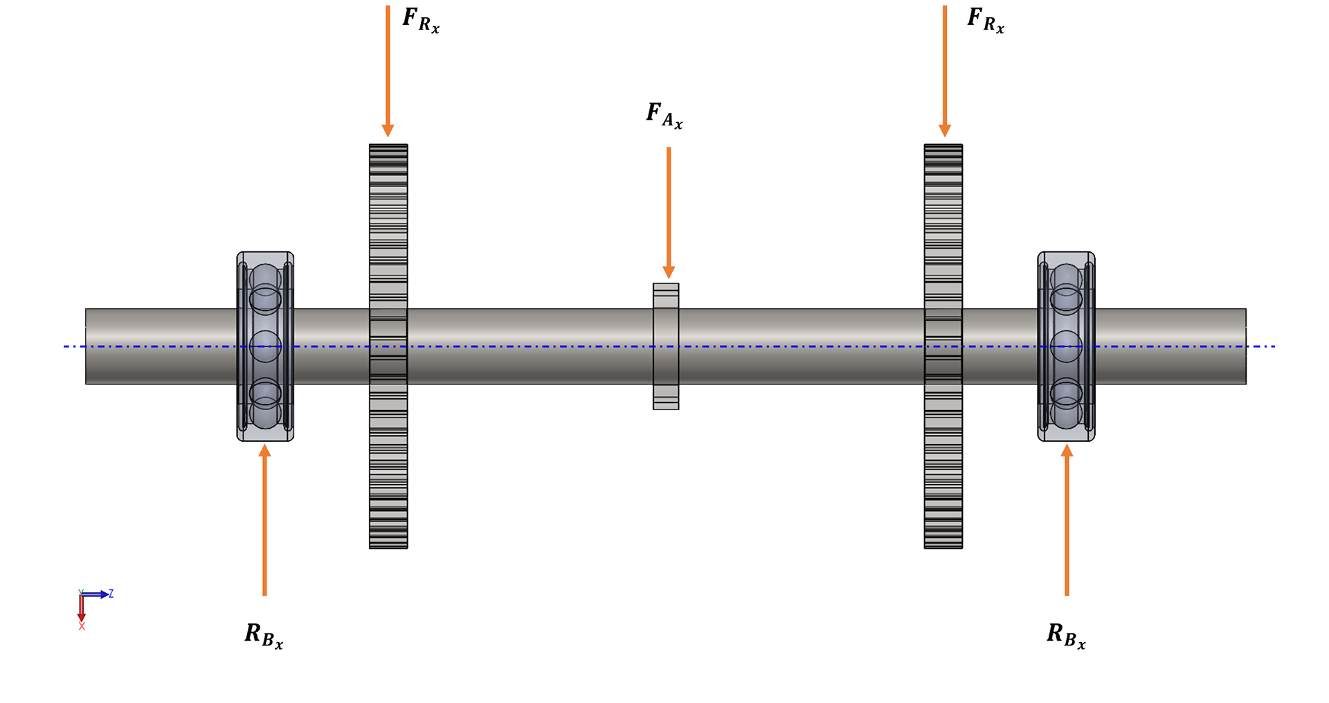
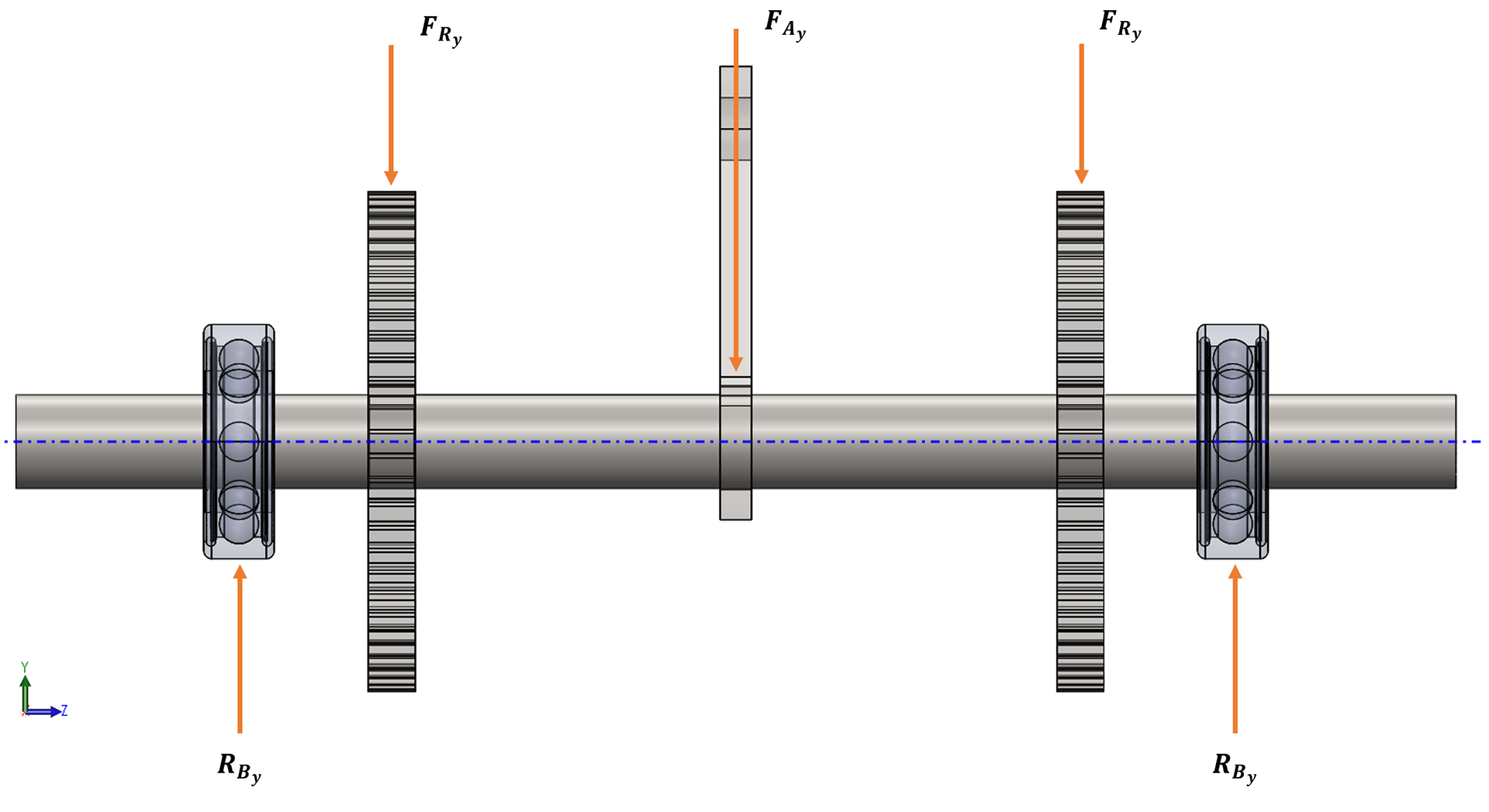
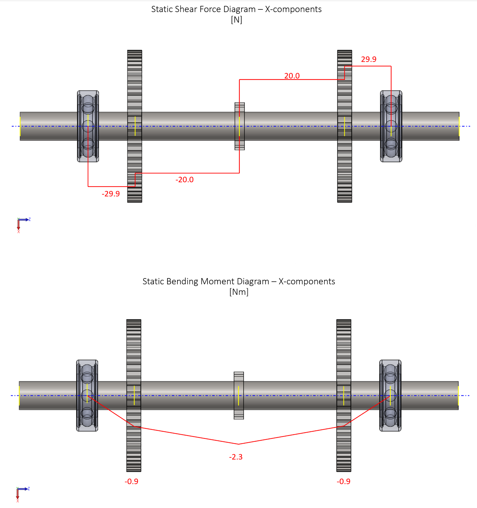
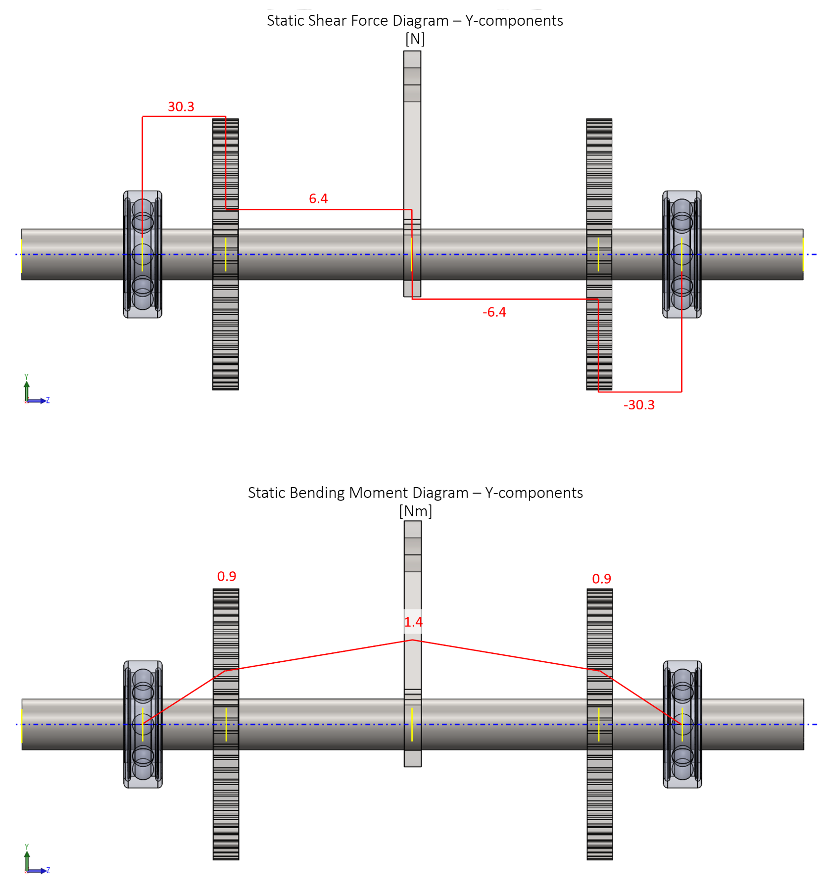
Each axle received a static and dynamic analysis where free body diagrams and shear moment diagrams were generated. The forces at each point of interest were broken into their X and Y components (radial forces). In the above set of images, the ratchet axle was analyzed. To calculate whether or not each axle exhibited infinite life, different distortion energy criterion methods were used including the Goodman, Morrow, Gerber, and the Smith-Watston-Topper methods as per Shigley's Mechanical Design edition 11.


All axles achieved infinite life with the exception of the Goodman criterion for the dynamic loading case of the pawl axle.
Fatigue - Bearings
Sealed ball bearings were selected to bear the loads of each axle. Using the equation below, the desired loads were calculated for each bearing, which were compared to each bearing's load rating. For the two types of bearings selected, each desired load was well below the corresponding rated lives.


Fatigue - Ratchet & Pawl
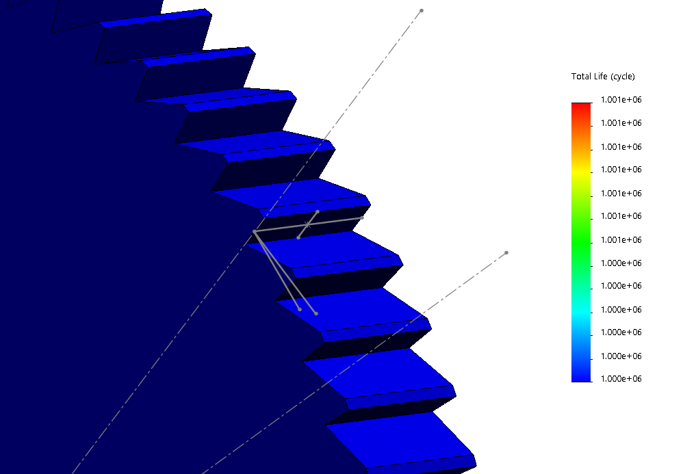
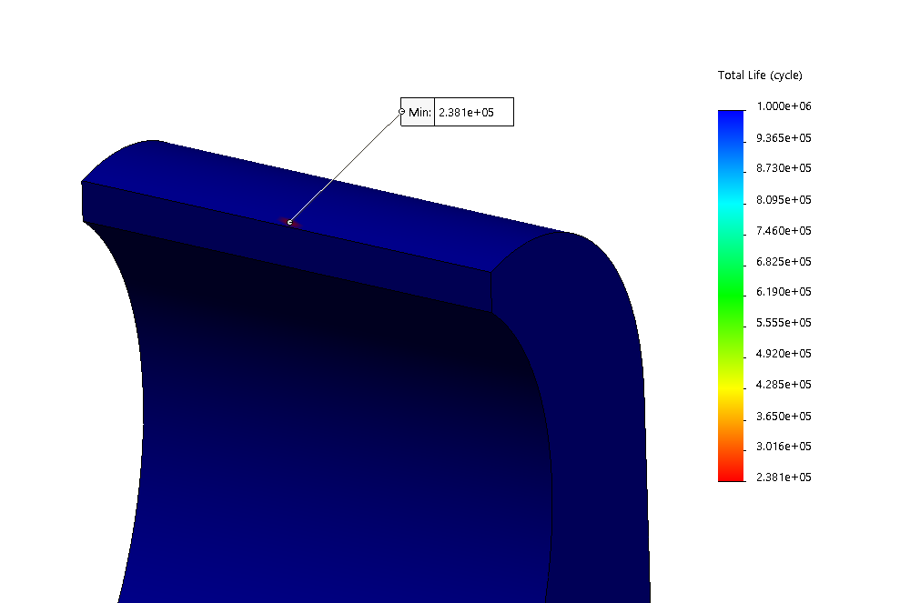
A fatigue analysis was performed on both the ratchet and the pawl with cyclical loads created by the large extension spring to return the restraint tubing to its open configuration using SolidWorks simulation. The fatigue test was performed using data from an AISI 302 (material of the ratchets and pawls) S-N curve. The applied load was represented as a point load for the purpose of this simulation. Given a contact force of 12.5 N at a pressure angle of 8°, it was determined that the ratchet would exhibit infinite life while the pawl would last 238,000 cycles.
Yielding
When a fault occurs during the duration of a rollercoaster, it may result in the application of an emergency break when a train enters its next breakstop. Besides the acceleration forces induced by the rollercoaster profile, the emergency breaking force was considered a parameter of which to design around. The components of interest were evaluated in terms of their yield strength, which were then translated to the resulting emergency break force required to cause the component yielding. Per ASTM 2291 standards, it was assumed the guest patron would weigh 185 lbs.

Yield - Axles
Similar to the fatigue analysis performed on each axle, shear moment diagrams were iteratively created for each axle based on the calculated von Mises ultimate strength. The maximum emergency breaking force was solved for statically based on the force combined moments and torques acting on each axle. Above is an example of the shear moment diagrams of the ratcheting axle given the emergency breaking force.
Yielding - Ratchet & Pawl
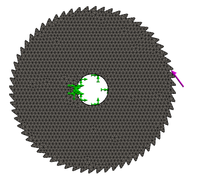
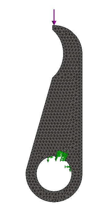
To perform finite elemental analysis on each model, a static simulation was created. Given the relatively low complexity of the models (in terms of model topography), fine meshes were created for both the ratchet and the pawl. Fixed constraints were applied to the center bearing circles to fix each model from rotating freely, and then the point loads were applied at the specified pressure angle for each model.
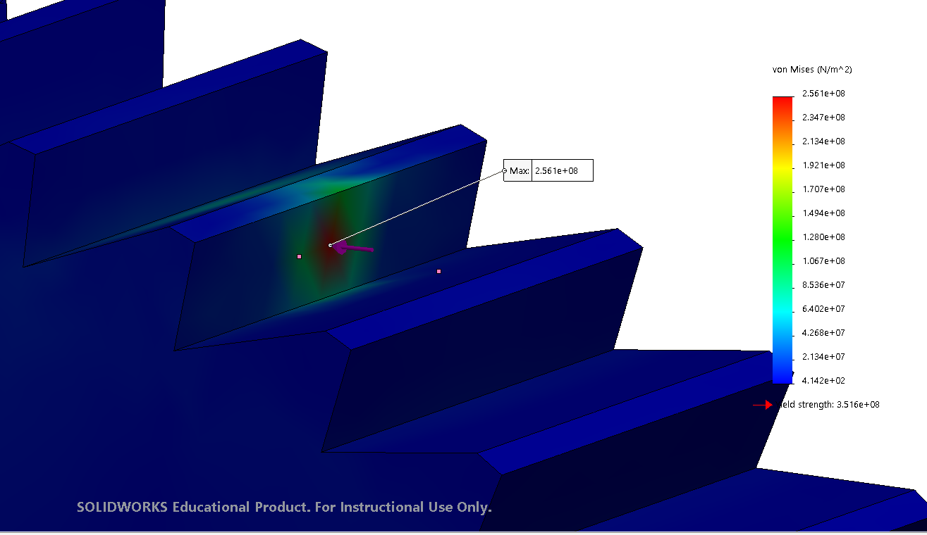
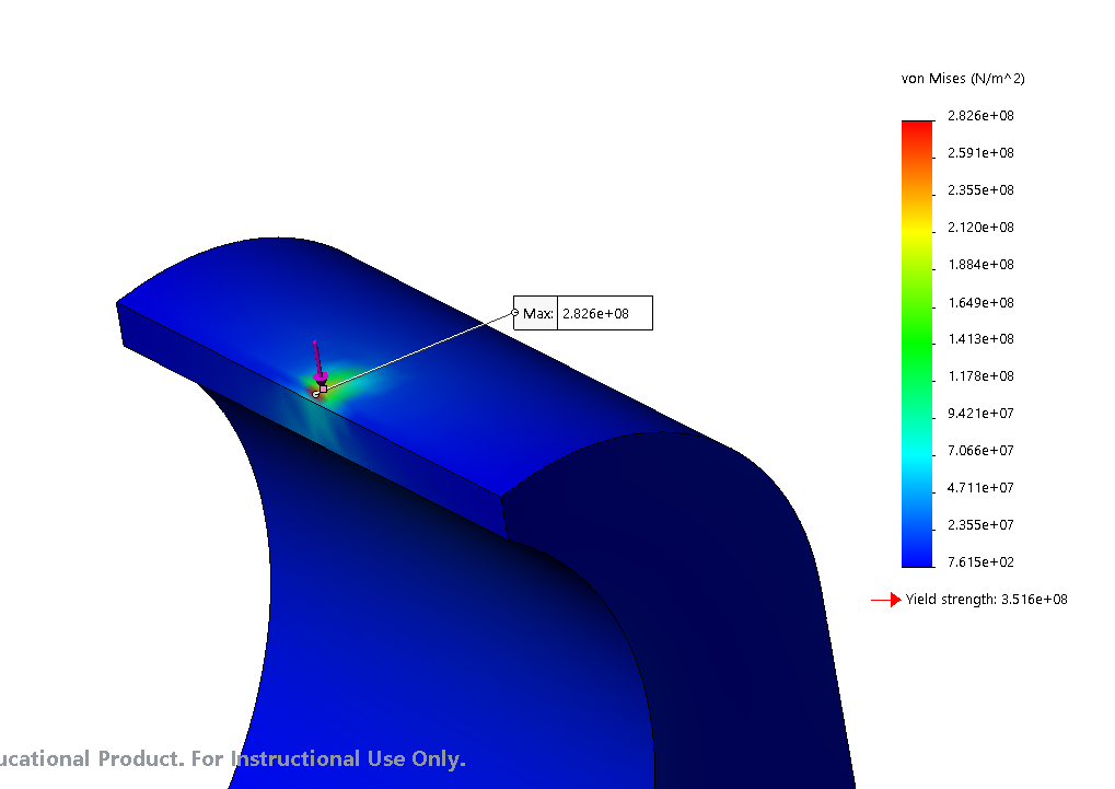
Based on the statics analysis provided previously, it was determined that the emergency break would create an 1821 N force between each ratcheting gear and its corresponding pawl. The force occurred at a pressure angle of 22.4° , which was measured relative to the center of the ratchet and the horizontal axis, while the pawl’s 22.4° pressure angle was measured relative to the pawl’s contact point and its bearing circle.
Yielding - Extension Springs
Each spring was analyzed in terms of its spring body and hook yield stress. The forces induced on the spring were in their maximum state when the corresponding spring exhibited its local maximum deflection. Each spring had a suitable factor of safety to prove adamant spring selection for the desired functions.


