
TriBio Autonomous Bioreactor
During the Fall 2020 semester, I worked with a group of 6 other students on a senior design project that consisted of developing a prototype design of an autonomous bioreactor capable of performing a variety of cell culturing functions. We were tasked with working with our client, the University of Florida Biofoundry, to tailor our product to meet a set of 35 customer requirements. The project served a variety of difficult challenges, as none of our team had previous experience working with lab/medical devices. Fortunately, this obstacle led to us coming together as a group to combine our diverse backgrounds to develop a product we are proud of.
My roles in this project consisted of team leadership, system integration, finite element analysis, and an emphasis on mechanical design.
Product Overview
Traditionally, a cell culture is performed by first preparing a well plate/conical tube with a bacterial fluid and then shaking the mixture in a linear/orbital shaker. Once complete, the well plate/conical tube is manually removed from the shaker and placed into an incubation unit that regulates cell temperature and atmospheric conditions for a given period of time. From there, the well plate/conical tube is inserted into a microplate reader where the bacterial culture's fluorescent intensity (FI) and optical density (OD) can be measured.
The TriBio Autoreactor can perform three separate cell culture experiments simultaneously by combining the capabilities of four standalone machines that are currently needed for bacterial culturing within one autonomous system. The four standalone machines referenced include a precision liquid handling system, a microplate reader, a shaker system, and an incubation unit. The greatest difficulty in this problem was determining a way to integrate each one of these systems into one product, given that at the time of this project, no such product had existed.
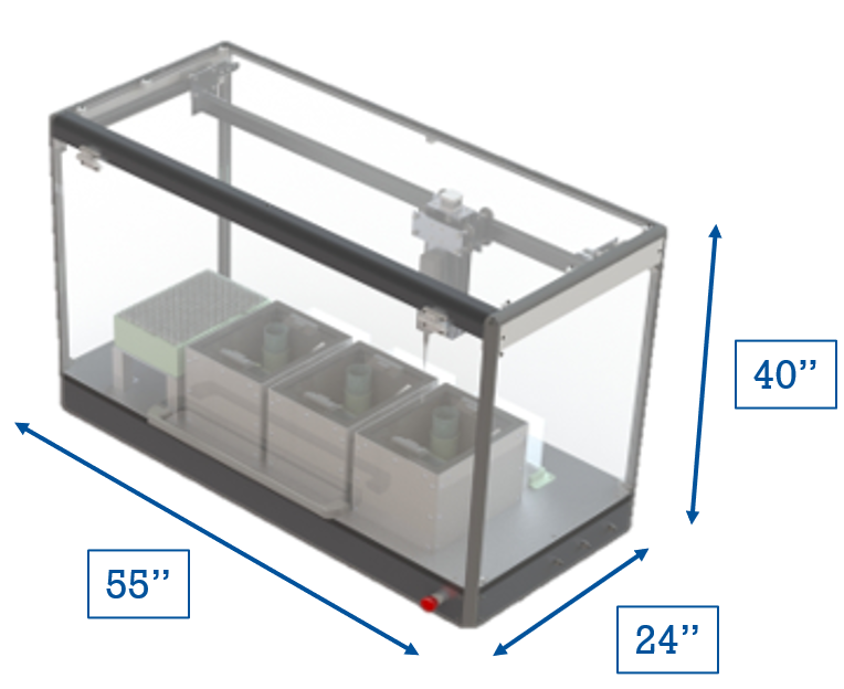
The TriBio Autoreactor has an estimated weight of 190 lbs, an approximated assembly time of 2.25 hours, and a production cost of $10,870. Cell culturing is achieved in this product due to its distinct subsystems, which include the product housing, gantry, liquid handling system, culture modules, shaker system, temperature control system, atmospheric control system, and the OD/FI sensor system.
subsystem overview
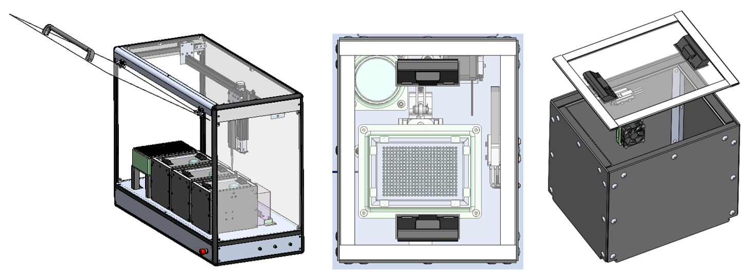
Product Housing
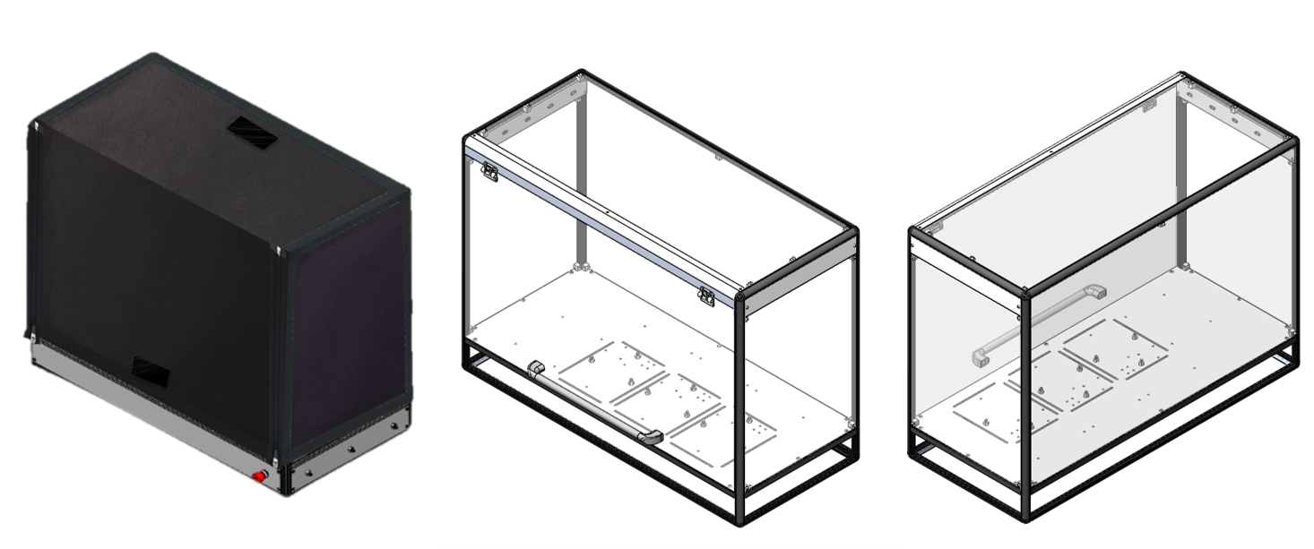
The product housing consists of a an 80/20 aluminum frame with lightweight polycarbonate panels. The front panel includes a handle and is attached to the housing using friction hinges to allow for the panel to remain open for loading well plates/conical tubes into the product. To prevent photobleaching from the laboratory environment, a blackout polyvinyl cover can be added, which can be detached using either magnets or zippers.
Gantry
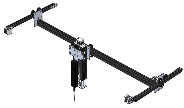
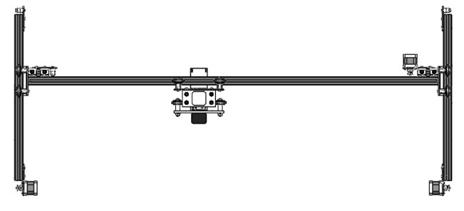
The gantry used in this product permits XYZ motion using stepper-driven belt drives for the X and Y axes and a stepper driven lead screw for the Z axis, where motion in each axis is facilitated by 80/20 roller carriages. The Z axis is home to the mounting of the liquid handling system and the laser diode used for measuring FI/OD.
Liquid Handling System
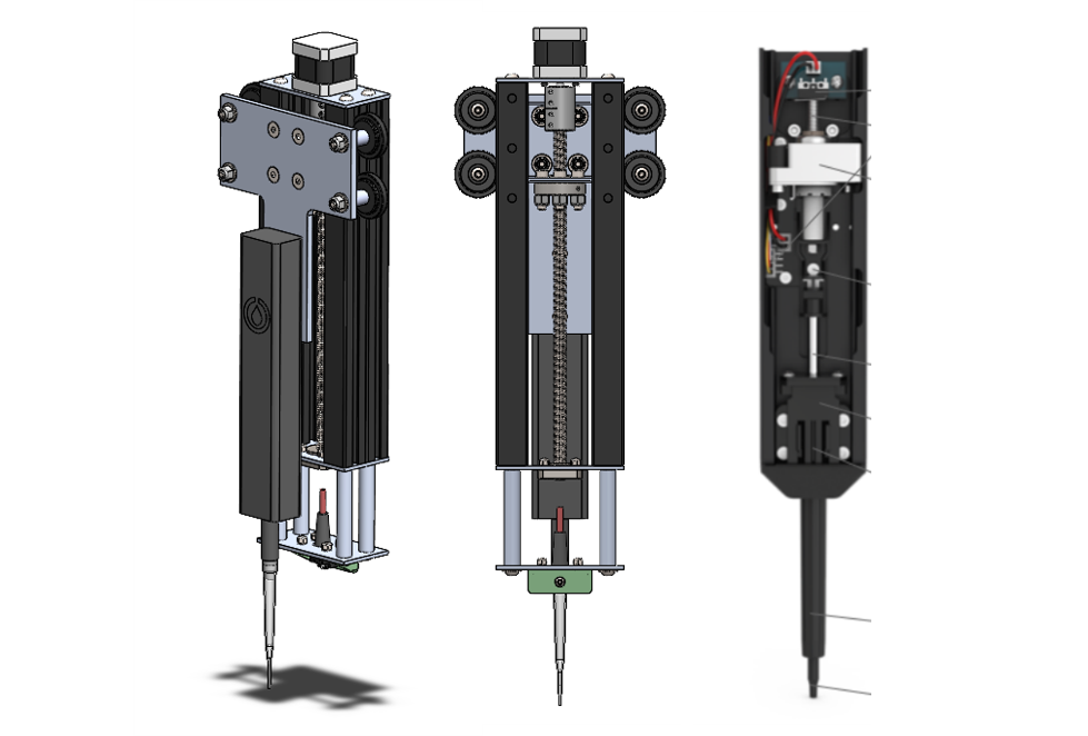
The liquid handling system consists of a mounted Opentrons P-1000 electric pipette to the Z axis bracket. The customer required the liquid handling subsystem to have the capabilities to dispense fluid in 1 μL increments with precision and accuracy less than 2% error, which is within the OTS product's capabilities. Additionally, the liquid handling device was required to have the capability of adding or removing fluid to/from a container, and given the leadscrew plunger mechanism inside the electric pipette (image on the right), fluid is able to be add/subtracted based on the direction of the pressure differential.
Culture Module
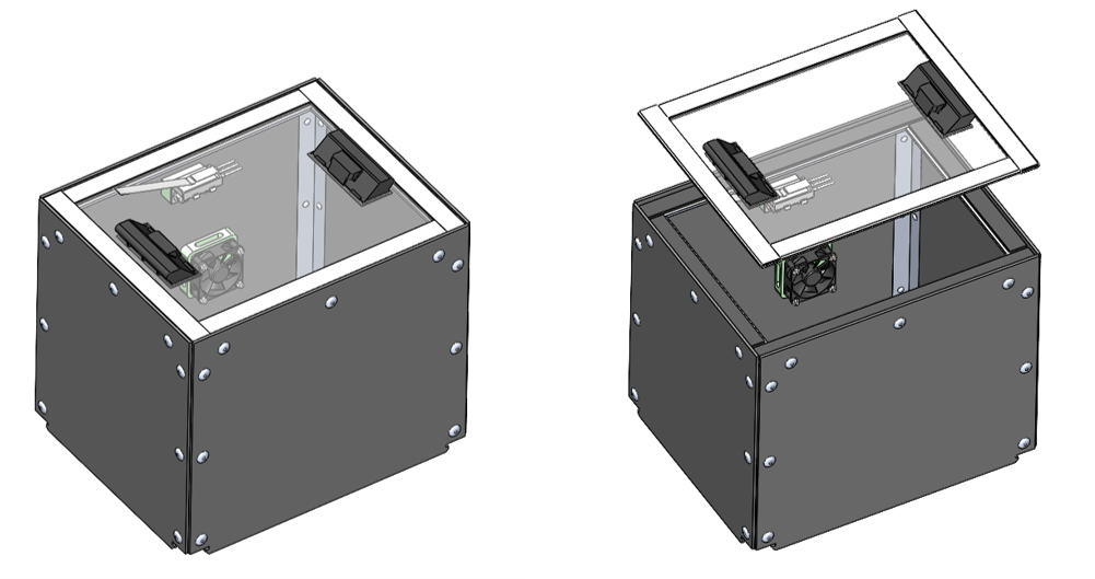
The device consists of three culture modules that encompass independent shaking patterns, atmospheric conditions, and temperature ranges. Each module is made from machined delrin walls connected by aluminum angle and rivets. Inside each module, there is a DC fan used for heat dissipation and a harsh environment limit switch used to provide feedback on whether the module is open. The lid panel is made of non-glare acrylic to allow for sensor transparency, and it is bordered by carbon steel sheetmetal pieces that create a seal with the rubber, magnetic gaskets. Each culture module snaps into the housing base plate, which allows for an atmospheric seal and ease of removal for maintenance access.
Shaker System
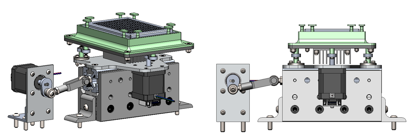
The customer required that the shaker system be capable of performing linear, orbital, and figure-8 shaking patterns. To achieve all three shaking patterns, a dual motor system was developed. A crank-slider mechanism using an 80/20 Unibearing is utilized for linear shaking, while a three dogbone off-center rotation is used to perform orbital shaking. When running both motors together, it is possible to achieve figure-8 motion as long as one of the motors is 180° out of phase of the other and running at the same speed. Each stepper motor has an integrated encoder to allow for closed-loop control so that a given well plate or conical tube can be positioned in 3D space for OD/FI sensing. Along with OD/FI sensing, the shaker system integrates the temperature control system.
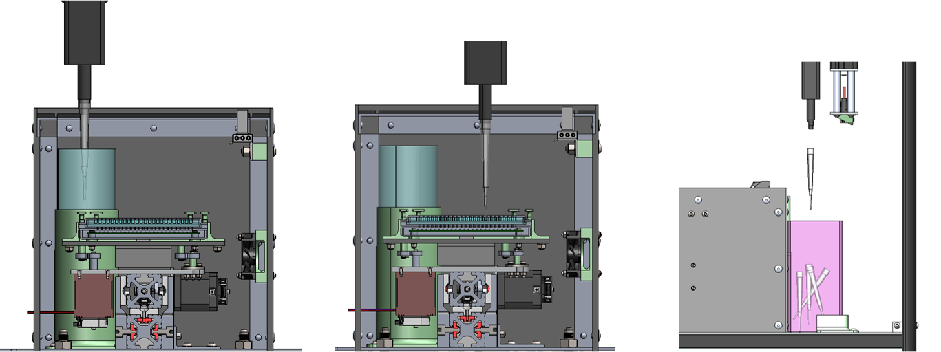
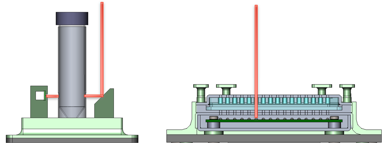
Temperature Control
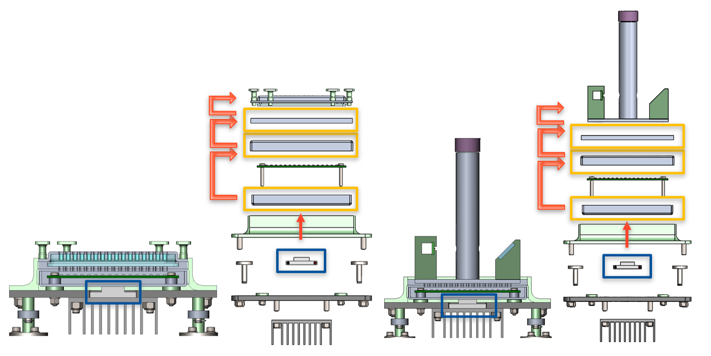
The customer requested that each well plate or conical tube be able to be heated/cooled to temperatures ranging from 4° C to 70° C with a uniform temperature distribution. To do so, a dual stage peltier plate (blue box in images above) was integrated into the shaker base plate. The peltier plate transfers heat to the well plate/conical tube via conduction through aluminum sheet metal parts (orange box), as can be seen in the first and third images above (section views). The two exploded images illustrate the conduction heat transfer from the peltier plate to the well plate/conical tube. A heat sink is in direct contact with the underside of the peltier plate, and the DC fan located in the culture module will facilitate the flow of excess heat by blowing parallel to the fins of the heat sink.
Atmospheric Control
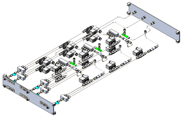
The atmospheric control system is located on the underside of the housing, and it allows for controlled mixing of nitrogen, hydrogen, methane, carbon dioxide, and oxygen in each culture module. The system consists of 15 solenoid valves, five flowrate meters, three 4-channel manifolds, five 3-channel manifolds, 3 vacuum pumps, and aluminum tubing. The 4-channel manifolds allow for mixing of nitrogen, hydrogen, methane, and carbon dioxide to go into each culture module, while the oxygen lines are separated to prevent potential combustion. Once an experiment is finished, the gases in each module are routed to the waste outlets using the vacuum pump.
OD/FI Sensor System
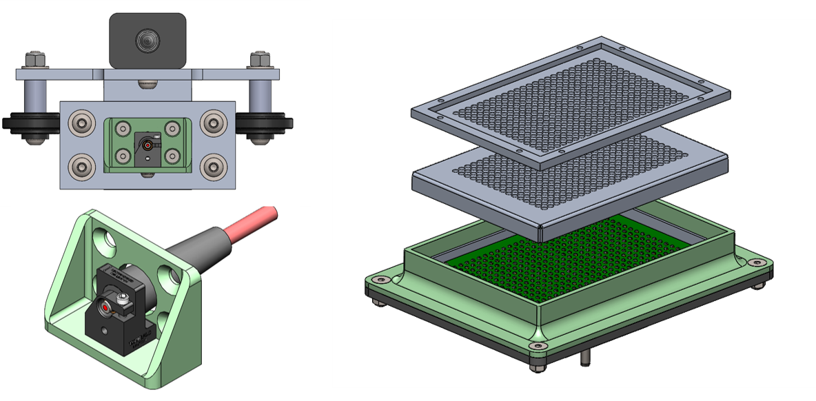
Optical density and fluorescent intensity are measured in each well plate/conical tube to allow for scientists to monitor bacterial growth/death during the culturing operation. OD and FI can both be measured by shining a light source through the bacterial fluid into a silicone photodiode, where the recorded intensity and wavelength from the photodiode can be helpful to scientists. The customer required a 640 nm wavelength light source with an intensity of 1 kW/cm^2, so a correspondingly powerful laser emitting diode was specified from Thor Labs. The photodiodes are arranged in a custom PCB configuration totaling 384 photodiodes, which corresponds with the maximum case of processing a 384 well plate.
Theory of Operation
Assuming the device is plugged into both a wall outlet and computer (USB), the user will first need to load a well plate or set of conical tubes into the culture module of interest by opening the front panel and removing the module lid. When the front panel is closed, it is engaged with a limit switch that allows for the gantry to move. When that panel is opened, the gantry will stop its motion to prevent any harm from contact with the user.
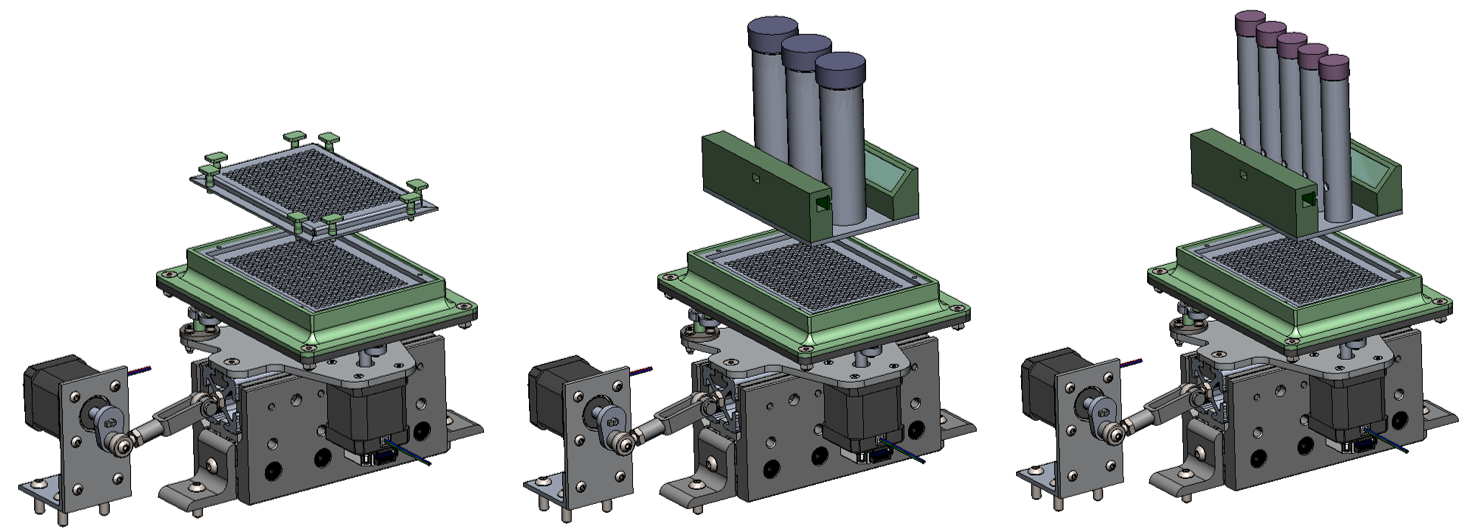
When it comes to loading the shaker plate, the user will have the choice of selecting a well plate or a set of conical tubes. Given that the length and width of a well plate remain constant regardless of the size, the user can select any sized well plate ranging from 6 well to 384 well. The well plate has a perforated aluminum sheet metal cover that is plugged into the mounting plate to allow for conduction of the well plate to occur in a sandwich fashion. The perforation of the sheet metal cover is spaced to a 384 well configuration pattern (4.5mm spacing), and this spacing will be sufficient to allow for FI/OD sensing to occur for any sized well plate.
For conical tubes, the user has a choice of selecting three 50 mL conical tubes or five 15 mL conical tubes. The mounting plate for the conical tubes has the same dimensions as a well plate, so it can be inserted similarly to a well plate. Unlike the well plate, the conical tubes cannot have their FI/OD measured axially, so a set of a 45° mirror and a photodiode strip are mounted to each conical set to permit transverse FI/OD measuring.
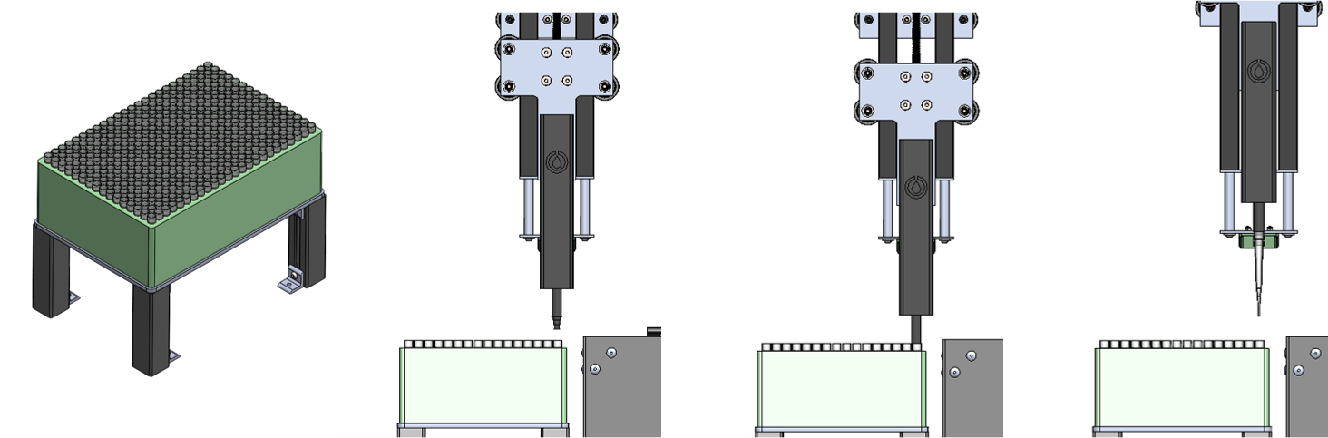
Once the well plates/conical tubes are loaded, the liquid handling device needs to distribute fluid into them. To do so, the electric pipette will need to pick up a 1,000 μL pipette from the 3D printed nozzle cavity (far left image). The electric pipette hovers over a sterilized nozzle tip, translates downward, presses into the nozzle tip opening, then moves to the open culture module to begin the fluid dispensing process.
Within each culture module, there is a 240 mL fluid container that the user can fill with the bacterial mixture of their choice. The electric pipette will then go back and forth between the fluid container and the well plate/conical tube until the well plate/conical tube is filled precisely.
The customer requested fluid addition and subtraction from each well/tube and to do so without any cross-contamination, so to prevent cross-contamination, plastic containers were installed at the back of each culture module to receive unsterile nozzle tips from the electric pipette's plunger ejection mechanism. Once a nozzle tip is ejected, the electric pipette can return to the nozzle tip cavity and retrieve a sterile tip and repeat the process. The cavity is configured to hold 384 nozzle tips, which will satisfy the worst-case scenario of transferring fluid from a finished 384 well plate. Once the experiment is complete, the user can manually remove the plastic tip container and refill the 3D printed cavity.
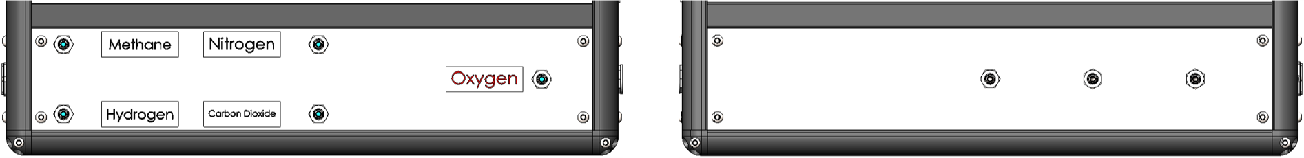
Once the well plate/conical tube is loaded with its bacterial mixture, the user will ensure the lab-stored gases are plugged into the proper inlet ports (left image). Additionally, the user will then check the opposite side of the device to ensure the outlet ports are routed to a safe gas removal chamber within the lab.
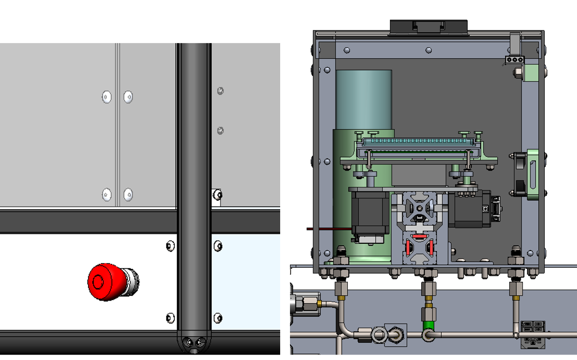
The user will then place the lid back on the culture module, which will activate the limit switch to allow for cell culturing in that module to begin. The user will then close the front panel and enter the experimental characteristics into the computer program to begin the experiment. The program will have its own way to cancel an ongoing experiment, but for the sake of convenience, a twist and push emergency stop was installed to the front panel of the device.
While a well plate/conical tube is in the process of culturing, the user can probe for FI/OD readings by scheduling habitual readings or instantaneous readings. The shaker will ensure the well plate/conical tube is at its resting position, and the 640 nm laser will shine through the non-glare acrylic lid and trigger the photodiodes of interest.
technical Analysis
Shaker Dynamic Analysis
A SolidWorks rigid body dynamic analysis was performed on the three different shaking patterns of the shaker system to verify the selected motors. Certain bacterial mixtures have optimal shaking speeds of 300 RPM, so the dynamic study was conducted at 300 RPM over a time period of 4s.
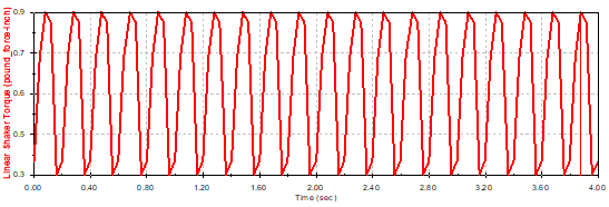
A maximum torque of 0.9 lb*in was required to conduct linear shaking at 300 RPM.
A maximum torque of 0.7 lb*in was required to conduct orbital shaking at 300 RPM.
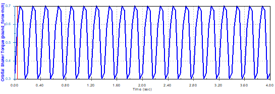
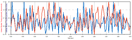
When running the figure-8 RBD analysis, both motors were set to 300 RPM, however the orbital shaker was set to run 180° out of phase with respective to the linear shaking motor. A motion plot of the well plate was tracked to validate the figure 8 motion.
When running both motors simultaneously, the maximum torques needed for 300 RPM speed were 1.4 lb*in and 0.8 lb*in for the linear shaking and orbital shaking motors respectively.

The torque/speed chart for the motors used in the shaker system is provided above. At a speed of 300 RPM (1,000 pps), the CUI NEMA17-16 emits a torque of 3.43 lb*in (55 oz*in). The motors are sufficiently selected and can run up to a maximum speed of 1,290 RPM (4,300 pps).
Housing Base Plate Modal Analysis
Given that the shakers are bolted to the base plate, a modal analysis was conducted to determine the critical frequencies to avoid from the shaker operation.
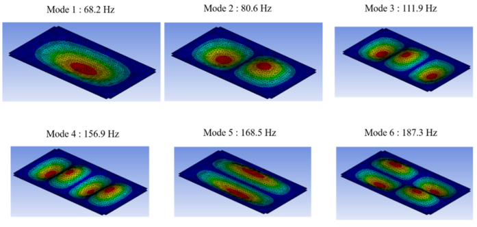
A modal analysis was conducted in ANSYS, where boundary conditions of the base plate were applied along the regions of contact between the base plate and the 80/20 frame. Six critical modes were identified at the frequencies in the image above, where the meshed areas in red represented deflections of roughly 0.75". This oscillating deflection would lower the fatigue life of the base plate and inhibit planar shaking, so these frequencies are to be avoided when selecting a shaking speed.
Housing Base Plate Structural Analysis
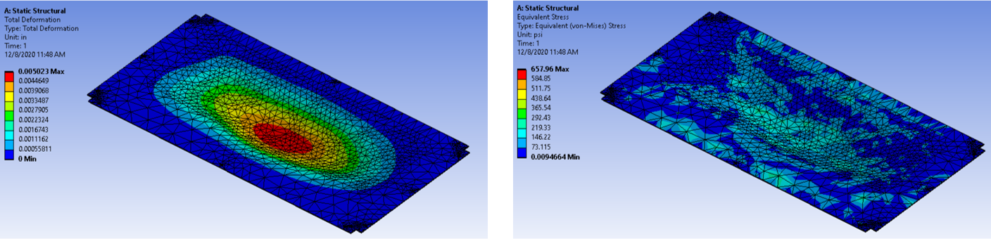
Aside from the shaking, the base plate was also the primary load bearing component in the device. The base plate is made from 1/8" 6061 AL, and it undergoes the weight of the shaker systems, culture modules, and other base plate mountables. This total load equates to a weight of 80 lbs, and for simplicity, the load was distributed uniformly to its area of contact with the base plate. The static structural analysis was conducted and resulted in a safety factor of 64.0 and a maximum deflection of 0.005", so the material selection and thickness was deemed more than sufficient for its expected loads.
Laser Intensity Calculations
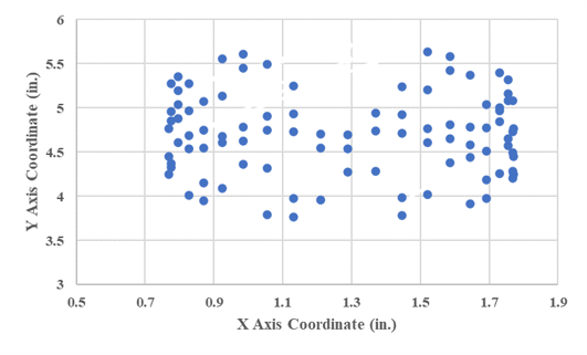
As stated previously, the customer requested a light intensity of 1 kW/cm^2 emitting from the laser. Given that light intensity is proportional to the inverse of the distance squared, it was expected that the intensity would decrease nonlinearly as a function of distance (see graph below).
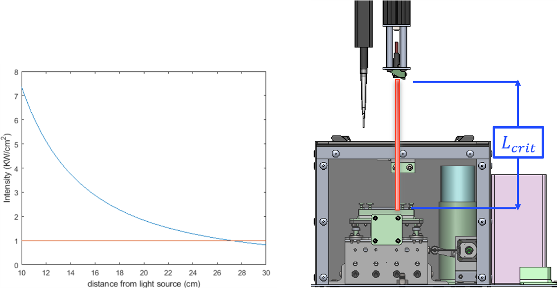
The specified laser has an output power of 150 mW and an emitting diameter of 1.6mm (area of 2.01 mm^2). A flux was calculated from these values at 7.4 kW/cm^2, and this value was found to decrease to a 1 kW/cm^2 flux at a distance of 27.13 cm (10.6"). For FI/OD to occur at an intensity of 1 kW/cm^2, the laser will need to be located 10.6" away from the integrated photodiodes.
One-Dimensional Heat Transfer (Conduction)

To validate whether the selected peltier plate was capable of performing the heating/cooling operations as required, a one-dimensional resistance circuit was developed. It was determined the peliter plate was capable of producing the power need for 70° C heating and 4° C cooling.
Transient Heat Transfer Analysis
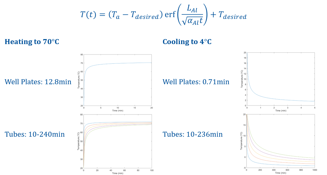
A transient heat transfer analysis was conducted to determined how long it would take to heat/cool the well plates/conical tubes within each culture module. For simplification, a 1D semi-infinite solid with constant boundary temperature assumption was applied. The transient analysis utilizes an error function that illustrates the lower thermal efficiency when reaching the extrema temperature values. For example, in both the well plates and conical tubes, intermediate temperatures such as 50° C or 10° C can be attained rather quickly, but the peltier plates lose efficiency as the ΔT value increases. Given that the conical tubes are encased in a much longer aluminum enclosure than the well plates, it is expected to take significantly longer to achieve uniform heating/cooling at the extrema temperatures. For a scientist looking to run experiments at 70° C or 4° C, they would more than likely need to set the module to a preheat mode before loading the fluid into the tube.
Additional Product Information
The Team

A special thanks to the hard work from each member of the senior design team. Each member had their own unique set of skills that helped elevate this product, and we learned how to apply those individual skillsets in a group environment to create a successful product.