
Excavator Arm Analysis
The objective of this project was to design an excavator arm to full scale and perform both a rigid body dynamic (RBD) analysis to size the actuators and examine the inertial effects of the motion profile on the structure by performing a transient analysis.
Mechanical Design

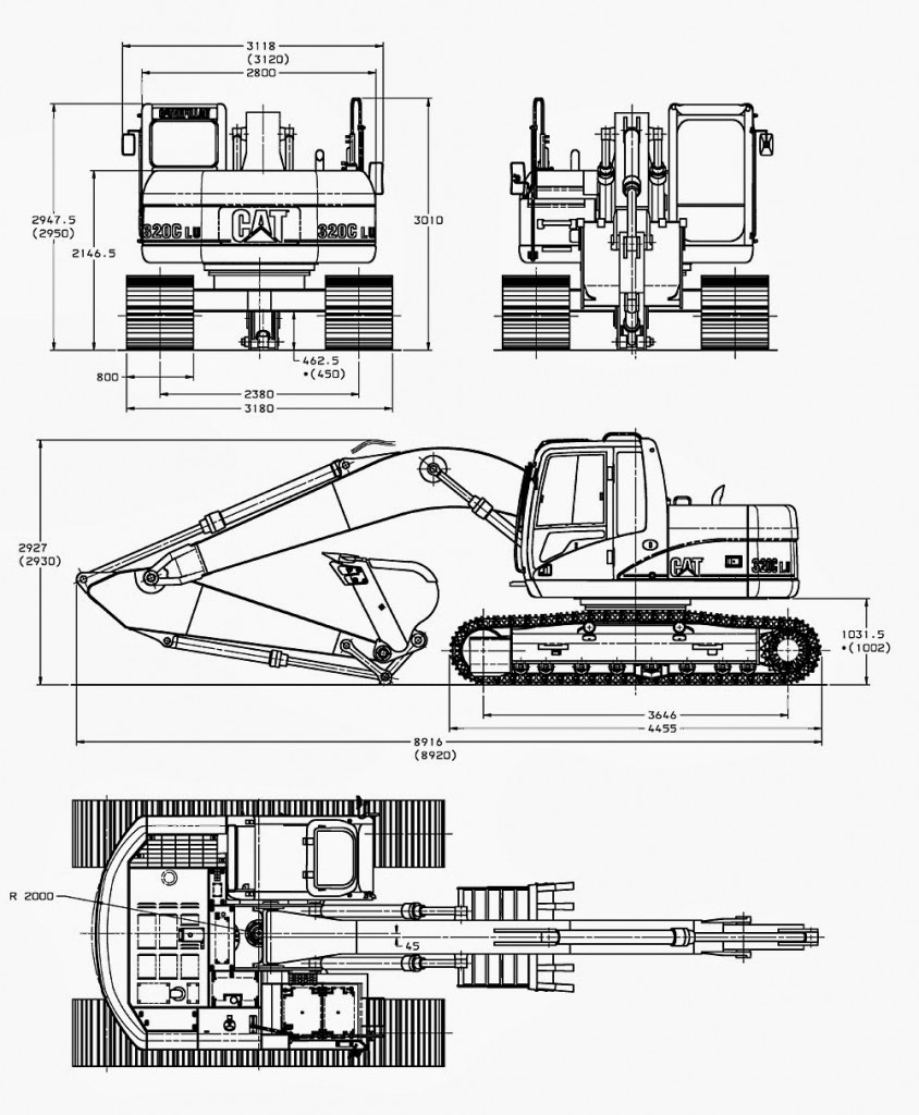
The excavator arm consists of four primary structures: the base, the boom, the dipper, and the bucket. It is modeled from the Caterpillar 320C excavator reference dimensions shown to the right (found online). For simplification, all structural components and linkages were specified as ASTM A36 with a total system weight of 8,040 lbs (not including hydraulic fluid weight contribution).
Rigid Body Dynamic Analysis
The excavator model was simplified for the RBD by removing the pins/split rings and using hinge mates about the axes where the pins were originally located. In SolidWorks motion analysis, linear motors were applied at each piston rod, and a motion profile was created using forward kinematics. At the instance where the arm appears to scoop dirt, a dead load representing the weight of the dirt was added to the interior volume of the bucket (78 lb/ft^3 dirt density resulting in a 4,240 lb load). The corresponding operational thrust and velocity parameters were determined for each actuator based on the position profile.


Magnitude Thrust [lbf] and velocity [in/s] specifications for each Boom actuator


Magnitude Thrust [lbf] and velocity [in/s] specifications for Dipper actuator


Magnitude Thrust [lbf] and velocity [in/s] specifications for Bucket actuator


Magnitude Torque [lbf] and angular velocity [deg/s] specifications for base slew ring motor
Transient Analysis
A static structural analysis is performed to calculate forces, stresses, and displacements on a structure where the loads do not change with respect to time and location. Generally, these types of analyses can be helpful in determining the strength of static structures that aren't induced by significant inertial load. However for dynamic systems, transient analyses (also known as time-history analysis) can be performed to determine the dynamic response of a structure under time dependent loading. Transient analyses also account for the inertial affects of the system, so the accelerations created by the motion profile of the arm are factored into the stress response. For the sake of this project, the dipper component was analyzed transiently.

A design study was created in SolidWorks where the dipper was meshed using triangular elements of size 2" (moderately fine with respect to the size of the dipper). A fixed hinge constraint was added to the two hole locations depicted above to restrict 3 translational DOF and 2 rotational DOF, thus giving an approximation of how the dipper is expected to move in reality.
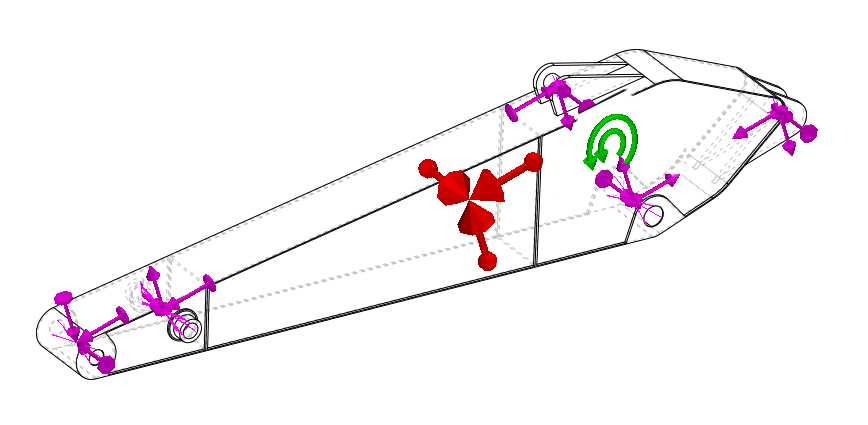
The loads calculated from the RBD were imported into the design study as time-variant remote forces/moments, angular accelerations, and angular velocities. In the image above, the remote loads (purple vectors) were applied at each pin/clevis location to represent the forces/moments transferred from the hydraulic actuators/pins. The effects of gravity were included (red vectors) within the context of the dipper configuration. Lastly, the imported rotational accelerations/velocities (green torsion) were included to account for the inertial affects of the profile.
The video above illustrates the transient response of the imported loads calculated by the RBD. For the sake of computation time, the transient analysis was performed using a 15 frame step, so time-variant loads were imported roughly every 0.6 seconds from the RBD. The von Mises stress was recorded for a total of 32 frames with a peak von Mises stress of 28.2 ksi occurring at frame 14 (0:07). It is worth noting that the inclusion of the dirt load was added between frames 11 and 25 (0:05 - 0:12) , so it was expected that the recorded stresses within this frame/time range would be higher than outside the range. The difference turned out to be approximately a factor of 10 for the excavator arm being loaded with 4,240 lb of dirt. Given the ASTM A36 yield strength of 36.3 ksi, the transient response resulted in a minimum non-loaded (no dirt) factory of safety of 6.95 and a minimum loaded (4,240 lb of dirt) factor of safety of 1.28. To improve the results of the transient study, the dipper mesh could be refined to smaller elements and the time step could be decreased to get a more fluid representation of the stress flow. However this would greatly increase the computation time, so this study is sufficient for determining an approximation of the maximum stresses experienced operationally.